

Electric control valve ZDLP electric single seat membrane ZDLM electric sleeve control valve
Electric control valve ZDLP electric single seat membrane ZDLM electric sleeve control valve
Standard signal 4~20mA DC, convert this to the up and down displacement corresponding to the input signal, automatically manipulate the valve, change the opening displacement of the valve, so as to achieve the process pipeline fluid medium such as pressure, flow, temperature, liquid level, etc. Automatic adjustment control of parameters.
ZAZP type electric control valve can be divided according to the mode of action;
Positive effect: electric closed type-normally open type (the valve position moves downward when the electric signal increases), "Type B"
Reaction: electric open type-normally closed type (the valve position moves upward when the electric signal increases), "K type"
ZAZP electric control valves are widely used in the automatic adjustment and remote control of industrial production processes such as chemical industry, petroleum, metallurgy, power station, light textile, papermaking and pharmacy.
There are standard type, bellows sealed type, jacket insulation type and other varieties. Product pressure grades are PN1.6 4.0 6.4MPa; nominal diameter DN20~300mm; applicable fluid temperature is -40~+450℃; it is used according to temperature Different valve covers can be divided into normal temperature type and high temperature type; flow characteristics have equal percentage (logarithmic) and linearity.
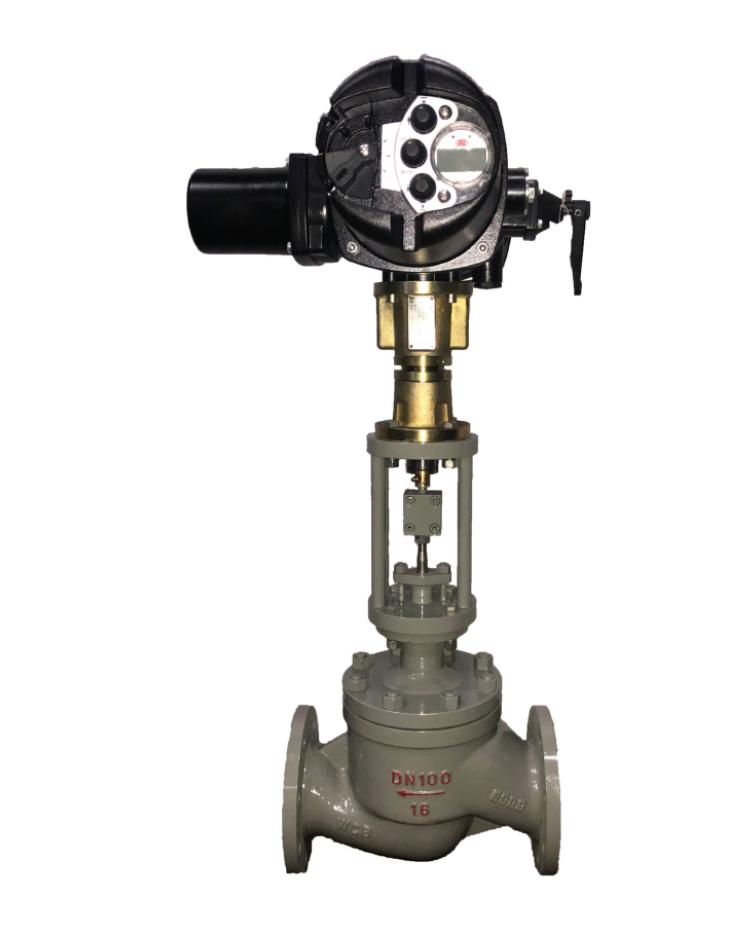
ZAZP electric single-seat control valve is composed of M8 straight electric actuator and straight-through low flow resistance single-seat valve. It has only one valve seat and one plunger-shaped valve core, which has good sealing performance. The guiding part adopts (upper and lower double guide type or The bushing top guide type) structure has the characteristics of large guide area and strong anti-vibration performance. It is suitable for occasions with strict requirements on the amount of medium leakage. However, due to the valve structure, the unbalanced force on the valve stem is relatively large. Especially in the working condition of large nominal diameter, this valve is only suitable for occasions with small working pressure difference.
Electric control valve actuator
型號(hào)2SB | 2SB6010——2SB6013 | 2SB6010——2SB6013 | 2SB6021 | |||||||||
推力N | 2000-8000 | 2000-8000 | 16000 | |||||||||
行程 | 10 | 16 | 25 | 30 | 18 | 30 | 40 | 60 | 30 | 50 | 60 | 100 |
全行程時(shí)間S | 8 | 12.5 | 20 | 24 | 15 | 24 | 32 | 48 | 16 | 30 | 37 | 62 |
M86+L8 series linear electric actuators can also be used with assembled instruments and TA instruments. It uses 220V power supply as the power of 4-20mmA.DC, and converts this into a linear displacement of the output shaft corresponding to the input signal. Operate the regulating valve or other terminal mechanisms to complete the automatic adjustment task, or equip an electric operator to realize manual remote control.
The instrument has three control modes: continuous adjustment, manual remote control, and on-site manual operation. The automatic adjustment system using M8 series linear electric actuator needs to be equipped with M8610 type actuator, and L8210 type linear conversion mechanism can realize the automatic adjustment system. Manual ←→ automatic undisturbed switching.
Performance index of electric control valve
項(xiàng)目 | 指標(biāo) | |
基本誤差% | ≤±5.0 | |
回差% | ≤3.0 | |
死區(qū)% | ≤3.0 | |
泄漏量 | 單座閥 | 10-4×閥的額定容量 |
雙座閥 | 10-3×閥的額定容量 | |
套筒閥 | 10-3×閥的額定容量 | |
Electric control valve allowable pressure difference
使用情況 | 閥芯處于流開(kāi)狀態(tài),關(guān)閉時(shí)閥后壓力P2=0 | ||||||||||
公稱通徑 | 閥座直徑 | 執(zhí)行機(jī)構(gòu) | 允許壓差(MPa) | ||||||||
電動(dòng)單座調(diào)節(jié)閥 | |||||||||||
PN1.6(MPa) | PN6.4(MPa) | ||||||||||
20 | 10 | 12 | 15 | 20 | 400,1000,2500 | 公稱壓力 | 3.8 | 2.7 | 1.7 | 1.0 | |
公稱壓力 | 4.3 | 2.5 | |||||||||
25 | 26 | 400,1000,2500 | 0.5 | 公稱壓力 | 0.6 | 3.6 | |||||
32 | 32 | 0.4 | 公稱壓力 | 0.4 | 2.3 | ||||||
40 | 40 | 400,1000 | 0.7 | 1.0 | 0.7 | 1.5 | |||||
50 | 50 | 0.5 | 1.0 | 0.5 | 1.0 | ||||||
65. | 66 | 6400,16000 | 1.4 | 1.4 | |||||||
80 | 80 | 1.0 | 1.0 | ||||||||
100 | 100 | 0.6 | 0.6 | ||||||||
125 | 125 | 6400,16000 | 0.5 | 1.0 | 0.5 | 1.0 | |||||
150 | 150 | 0.3 | 0.7 | 0.3 | 0.7 | ||||||
200 | 200 | 0.2 | 0.4 | 0.2 | 0.4 | ||||||
250 | 250 | 16000 | 0.3 | 0.3 | |||||||
300 | 300 | 0.2 | 0.2 | ||||||||
Material of main parts of electric control valve
材料代號(hào) | C(WCB) | P(304) | R(316) | |
主要 零件 | 閥體,閥蓋 | WCB(ZG230-450) | ZG1Cr18Ni9Ti(304) | ZG1Cr18Ni12Mo2Ti(316) |
閥芯,閥座 | 1Cr18Ni9Ti(304)或司鈦萊合金堆焊 | 1Cr18Ni9Ti(304)或司鈦萊合金堆焊 | 1Cr18Ni12Mo2Ti(316)或司鈦萊合金堆焊 | |
閥桿 | 2Cr13 | 1Cr18Ni9Ti | 1Cr18Ni12Mo2Ti | |
填料 | V型聚四氟乙烯(F4),柔性石墨,不銹鋼波紋管 | |||
墊片 | 增強(qiáng)聚四氟乙烯 (F4),不銹鋼墊片,金屬石墨纏繞墊片 | |||
推桿,襯套 | 2Cr13 | |||
適用 工況 | 適用介質(zhì) | 水,蒸汽,油品類氣液體 | 硝酸堿類腐蝕性氣液體 | 醋酸類等腐蝕性氣液體 |
常溫型 | -30~+250 F4:≤200℃ | -40~+250 F4:≤200℃ | -40~+250℃ F4:≤200℃ | |
高溫型 | -30~+450℃ | -40~+450℃ | -40~+450℃ | |
Main technical parameters of electric control valve
公稱通徑mm | 20 | 25 | 32 | 40 | 50 | 65 | 80 | 100 | 125 | 150 | 200 | 250 | 300 | ||||
閥座直徑mm | 20 | 25 | 32 | 40 | 50 | 65 | 80 | 100 | 125 | 150 | 200 | 250 | 300 | ||||
額定流量 | 單座 | 5 | 8 | 12 | 20 | 32 | 50 | 80 | 120 | 200 | 280 | 450 | 800 | 1200 | |||
雙座 | 10 | 16 | 25 | 40 | 63 | 100 | 160 | 250 | 400 | 630 | 1000 | 1600 | |||||
套筒 | 全量 | 15 | 35 | 50 | 125 | 190 | 400 | 630 | |||||||||
0.6 | 9 | 20 | 30 | 75 | 115 | 240 | 350 | ||||||||||
額定行程L(mm) | 10 | 16 | 25 | 40 | 60 | 100 | |||||||||||
執(zhí)行器型號(hào) | 2SB6013 | 2SB6013 | 2SB6013 | 2SB6013 | 2SB6021 | 2SB6021 | |||||||||||
出軸推力N?m | 2000-10000 | 2000-10000 | 2000-10000 | 2000-10000 | 8000-16000 | 8000-16000 | |||||||||||
全行程時(shí)間S | 8 | 12.5 | 20 | 32 | 48/37 | 62 | |||||||||||
電源電壓 | AC220V 50Hz | ||||||||||||||||
輸入信號(hào) | 4~20mA DC 0~10mA DC | ||||||||||||||||
輸入阻抗 | Ⅱ型:200Ω Ⅲ型:250Ω | ||||||||||||||||
作用模式 | 電開(kāi)式(K)型,電關(guān)式(B)型 | ||||||||||||||||
流量特性 | 等百分比,直線,快開(kāi)性 | ||||||||||||||||
允許泄漏量(L/h) | 單座≤10-4×閥額定容量;雙座≤10-3×額定容量榨呆;套筒:≤10-3×閥額定容量 | ||||||||||||||||
固有可調(diào)比R | 30:1 | ||||||||||||||||
公稱壓力PN(MPa) | 1.6 2.5 4.0 6.4 | ||||||||||||||||